
OpenFeeder Now Live on GitHub!
My open source Pick and Place feeder is not live on GitHub! You can download the source files there.
Here is a quick overview: http://portfolioabout.me/openfeeder-open-source-smd-part-feeder-for-openpnp/
https://github.com/xboxhacker/OpenFeeder
Discussion about the feeder can be found at OpenPNP Google Group


K40-SmoothieLaser Breakout Board
I have a cheap Ebay China 40W CO2 laser. Commonly known as the K40. The software it comes with is, “OK”. But I want to do more with it. I read online that there are some RAMPS 1.4 upgrades with Marlin firmware. But I HATE compiling and flashing the Mega 2560. It is a real PIA! Then I came upon SmoothieBoard. Its a 32Bit control board for lasers, 3D printers and CNC. And it you need to make a change to the settings, you just enter edit a config file on an SD card and reboot…. NO RECOMPILE AND RE-FLASHING!!
I need to connect the SmoothieBoard to my laser, replacing the OEM control board. But the laser has a 12pin flat ribbon cable (FFC). So I made a breakout board! The board accepts the machine FFC and make its usable pins for the SmoothieBoard.
I went with the MKS Sbase Smoothie compatible board. It was a lot less money then the original Smoothieboard.


There is another board out there called the Middle Man Board. It does the same thing. I removed some of the outputs that were not needed, and made it much simpler.
Here are the Eagle Cad files for the board.
BOM:
- 1 PCB
- 1 FFC 12pin Female (PN A100331-ND Digikey.com)
- 1 4pin Terminal Bock (PN 277-1806-ND Dgikey.com
- 2 2Pin jumper header
Might want to pick up some JST connectors if you are going to use a knockoff Smoothieboard.
I will be selling board in my store if anyone needs one.
OpenFeeder – Open source SMD part feeder for OpenPNP
I owned some great Pick and Place equipment about 15+ years ago. My contract ran out for SMD manufacturing, so I sold all my machine. Now I have need for SMD PNP again. So I looked toward some opensource alternatives to the commercial machines. I can across OpsnPNP.org. The software so far seems great. But it is still in the BETA stages.
I gathered up a part list of thing I will need. Like motors, drivers, wire, t-slot…etc. I did some more research and started coming up with a design for my machine. But it seemed like there was not a great SMD tape feeder. Thus the OpenFeeder was born!
I wanted a feeder that could do lots of things, expandable and adaptable.


This work is licensed under a Creative Commons Attribution-NonCommercial-ShareAlike 4.0 International License.
DIY Tee Shirt Heat Press From A Griddle.
I needed a Tee Shirt Heat Press in a hurry! Didn’t have time to order one, and wait to get it shipped in. So, I made my own. (As you could have guessed)
This project was 100% FREE!! It was made from junk and scrap I had laying around the shop. It cost me NOTHING! And that’s the best price. LOL

I had an only griddle that i was using as a hot plate for SMD soldering. I used my chop saw and removed the rolled edge, that catches the grease. So I ended up with a smooth flat area in the center of the griddle. Then I used some scrap aluminum, and the original foot holes, to mount the holder arms too.

The base was made from some scrap T-Slot aluminum, left over form the grommet machine project. I added a piece of Birch ply wood that i cut to size of the griddle.
Here is the rising neck of the base.

Took some 1″ bar stock aluminum and made a pressing handle. Then attached the handle to the griddle part with the arms. The handle pivots on the base neck.


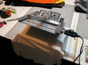
The finished product! It works great. But the heated area is a little smaller then a commercially available machine.
DIY Grommet Machine
I needed a new grommet machine for a second grommet size I use. I was able to find some in my price range, but the machine’s throat was not deep enough. All I could find was about 8-10″ deep. That wouldn’t work.

I got some T-Slot aluminum extrusions on ebay and made my own!

The machine is air powered. I got a 4″ bore cylinder on ebay for cheap! I made a mounting plate out of some scrap 1/4″ thick angle iron I had.
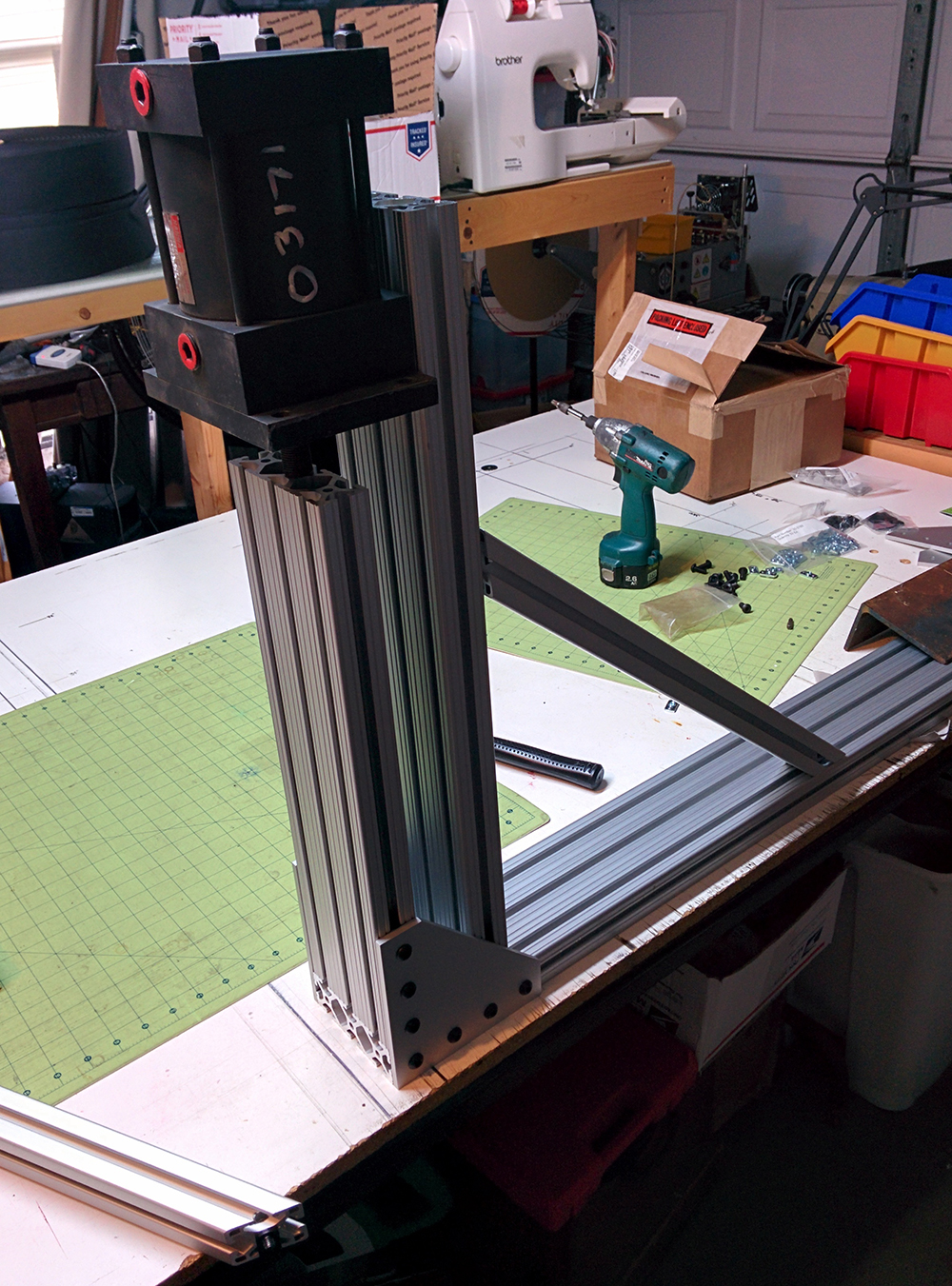
The depth of the throat of this machine is about 28″! The material slips down between the 2 sections of aluminum.

I got a cheap machine table from harbor freight, and mounted the grommet machine to it. It works, but my compressor does not have the air capacity to power it to its fullest. That’s the next buy.
Grommet Machine Auto Feeder
I own a grommet machine form the ’40s. United Shoe Machine Model F. The thing is a beast! A true work horse. I bought it on Ebay for $85, but it cost me almost $200 to ship it. But it is well worth it! The machine even came with the correct dies I needed. But it did not come with the auto feeder attachment.
This machine is is still popular. There are a few places that still have parts for it. I called one of them to get the feeder. They said it would be $2k!! WTF!! So I said no thanks. LOL And I embarked on making my own.
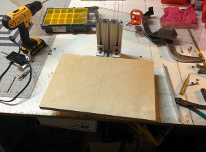
This design is close to how the OEM feeder would work. Since I had nothing else to go off of.

Step one, make a template.


Using the template, I made the body part from birch plywood. I then wrapped the outside edge of the plywood with 1/8″ aluminum. This is the part that the grommets will ride on. I counter sunk and screwed the aluminum to the plywood.

I took 1/16″ Aluminum with make the keepers, to keep the grommets on track. I used some spacers to keep them elevated off the main track.

So good so far! Gravity feeds the grommets to the lowest section, at the die.

I notched out the delivery end so the die will grab the grommet when the machine is activated. The machine has a cam at the top to move the feeder out of the way when the grommet is pressed.

Made a platform for the mixer. This will separate the grommets into the direction the feeder need.

Racked my brain for a while on how to make the bowl for the mixer. BAM! 6″ PVC clean out, even has a lid. Cut a small opening in the PVC for the grommets to exit ONLY in the orientation I want them to.

On the bottom of the mixer I installed a gear reduced 12VDC motor. The shaft is connected to a 4 prong head, with rubber gas holes ends. The motor turns the bowl full of grommets and spits out ONLY the ones in the correct orientation for the feeder.
DIY Hot Knife Gun
I needed a hot knife to cut some polypro webbing. Looked on Ebay, couldn’t find anything for a good price. The target was VERY LOW!!
SO, yep … I made my own!
I went to Harbor Freight and grabbed a 200W soldering gun, for about $13.

I had some 1/8″ brass rod laying around. Where the soldering tip would go, I used a 1/8″ drill to drill out the contacts. So the brass rod would fit inside them. The OEM tip was much smaller then 1/8″.

Bent the brass rod into a basic U shape, to get the width I wanted for the cut.

Then bent the legs back to match the opening of the soldering gun.

Here was the tricky part! I smashed it flat on a vise with a hammer. But it didn’t work. The brass fell apart. So I made a new one. This time I put the cutter in the gun, pulled the trigger, heated up the brass. Then smashed it flat. IT WORKED!

This thing works GREAT!! I cut on a piece of glass to keep from melting the table.
Modded Chinese 50″ LED Light Bar
A very good friend of mine came to me with an idea. He wanted a 50″ LED light bar for his Jeep, but he wanted it 100% UNIQUE!!!
Challenge accepted!
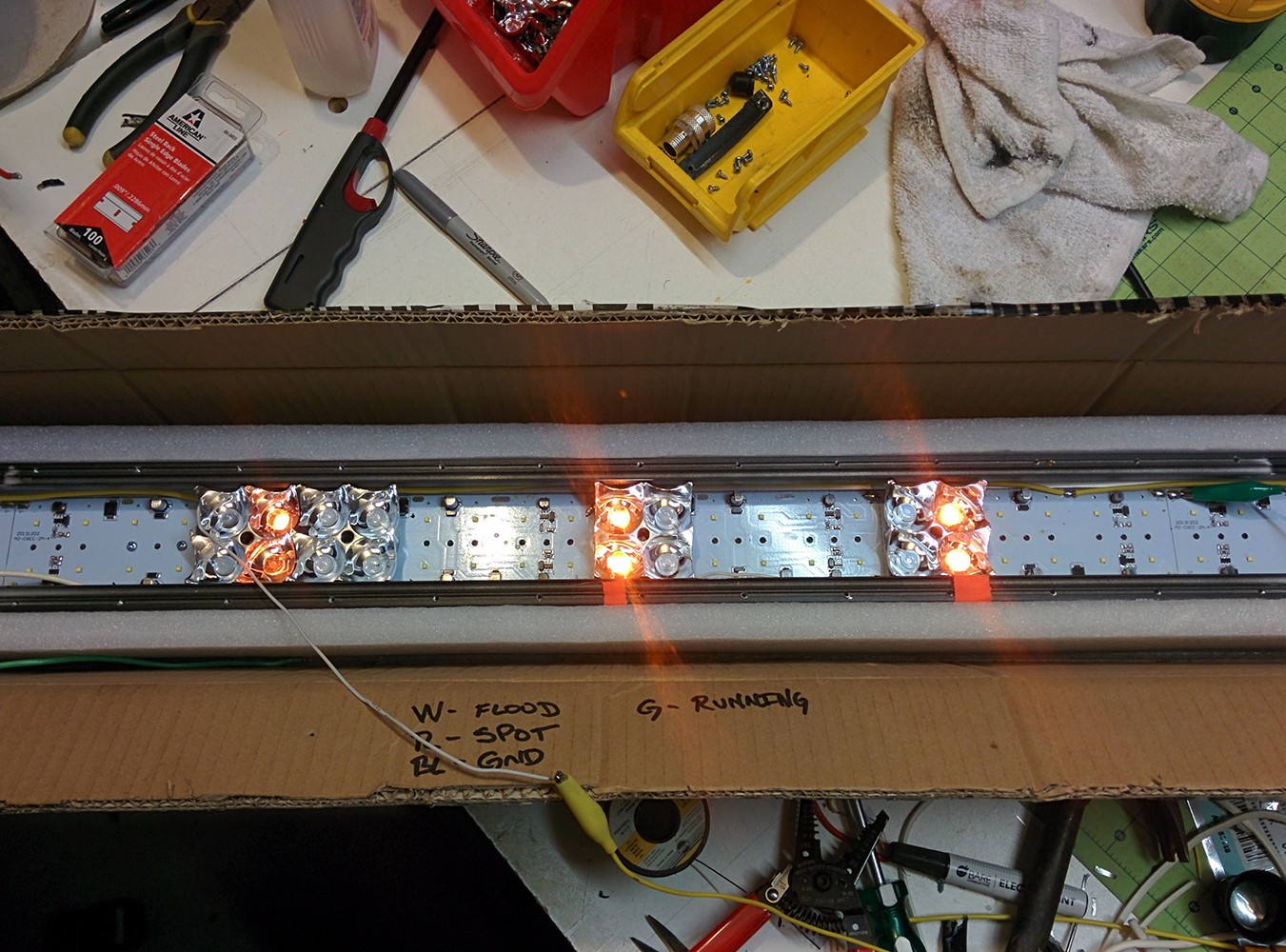
He was used to running diesel trucks with 3 amber marker lights above the cab. And that’s what he wanted this light bar to do.

I took apart the Chinese 50″ light bar, and came up with a design for a “add-on piggy-back” board. This board would have the new amber LEDs and the drivers for them. The design was such that I needed to remove a few of the OEM LEDs to make room for my new board. It was also designed so that the new amber LEDs would line up with the OEM lens. Here is the gang board from a board house I use. There are 8 boards on this one PCB.
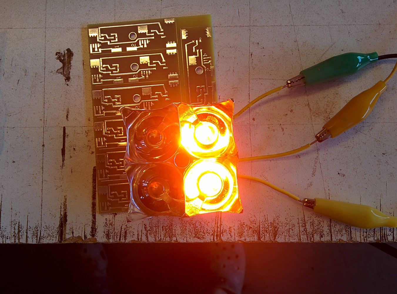
Bench test of the board design with the light bar optics. I used 5050 amber LEDs.

This is one of the 3 boards installed into the light bar. The little yellow things are the OEM LEDs. I took 2 of them out in this section. I just still 12VDC from the + rail.
This is all three add-on boards installed.

Another view.

This is how it looks installed on the jeep, all sealed up (MUCH better then the OEM Chinese had done)
He LOVED IT!!
DIY Jeep Wrangler $12 Fuel Check Valve
My 1997 Jeep Wrangler had a problem starting, I would have to hit the key twice to get it running. Even if I stopped for a second at 711 to get a soda. :/
The problem lies int he pump, that’s in the tank. It has a check valve that keeps fuel from draining back into the tank when the Jeep is off. But, the pump is good. So didn’t want to spend the money of replacing it, I just delt with the hard starting.
But i ended up getting sick of that! So i started a mission to make my own “in line” check valve. I went to my local Ace Hardware, and started looking at some brass fittings. I grabbed some part, went home, put it together and BABAM!!!! it works like a CHAMP!!!
This is not a fix, its just a bandaid! One day the pump will die, that’s when I will replace it.
Parts list:
- 2x – 5/16″ compression to 1/4″ npt
- 1x – 1/4″ npt to 1/4″ npt barrel
- 1x – 1/4″ chrome ball bearing
- 1x – 1 1/2″ spring. *must cover the ball, but not spring out when installed.
- 1x – yellow teflon pipe tape (DO NOT USE WHITE TEFLON TAPE)
- Small tubing cutter for fuel line
The ideas is NOT to have a ton of pressure on the spring and ball, you barely need any at all. You are just helping your fuel system. To much pressure on the spring and the pump wont get enough fuel to the fuel rail.
The setup is completely reversible! Simply take out the spring and ball, and use the compression fittings to link the fuel line together.

Here are the parts of the DIY check valve.
![IMG_20140218_130712[1]](http://www.williamhare.portfolioabout.me/wp-content/uploads/2013/12/IMG_20140218_1307121.jpg)
Stating of assembly. Ball bearing is already inside the brass, under the spring.
![IMG_20140218_142952[1]](http://www.williamhare.portfolioabout.me/wp-content/uploads/2013/12/IMG_20140218_1429521.jpg)
Installed in the Jeep!
Birth of a 3D printer – Part2

This is the CPU mounted on the bottom of the printer.

The hot bed is installed. The hot bed keeps the parts inplace while printing.

Mocking up the towers before making the wooden frame.

ALMOST DONE!!

First running of the firmware for the CPU.

I had to modify the switches to work with my printed parts.
Its all coming along nicely!!
